| Previously, an introductory part of the GIS and its components were discussed to pave the way for the GIS control circuits. Moreover, the single-line diagram example for a double-bus and a single breaker clarifies several concepts that are for the GIS only. It is challenging to comprehend and grasp the control circuits due to the interrelated components and functions that impose additional interlock schemes and control functions. Hence, a brief description of drawing tips and drawing examples was elaborated before delving into the actual article topics (control circuits). Broadly, control circuits are categorized into: - AC & DC auxiliary circuits
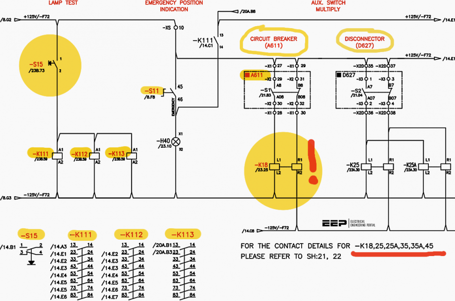
- DC of secondary (close/trip) for CB, disconnector, and ground switches
- Indication and alarm circuits
- SCADA indication and alarm circuits
- Equipment coil contacts arrangements and components details
- AC of secondary (CT & PT)
The first group shares similar concepts with the MV switchgear circuits in previous articles, so they were mentioned briefly. The second group includes many circuits-namely, breaker closing circuit, breaker trip circuit, and disconnector/ground switch close/open circuit. The breaker closing circuit requires so many conditions fulfillment before closing. | 


Comments
Post a Comment