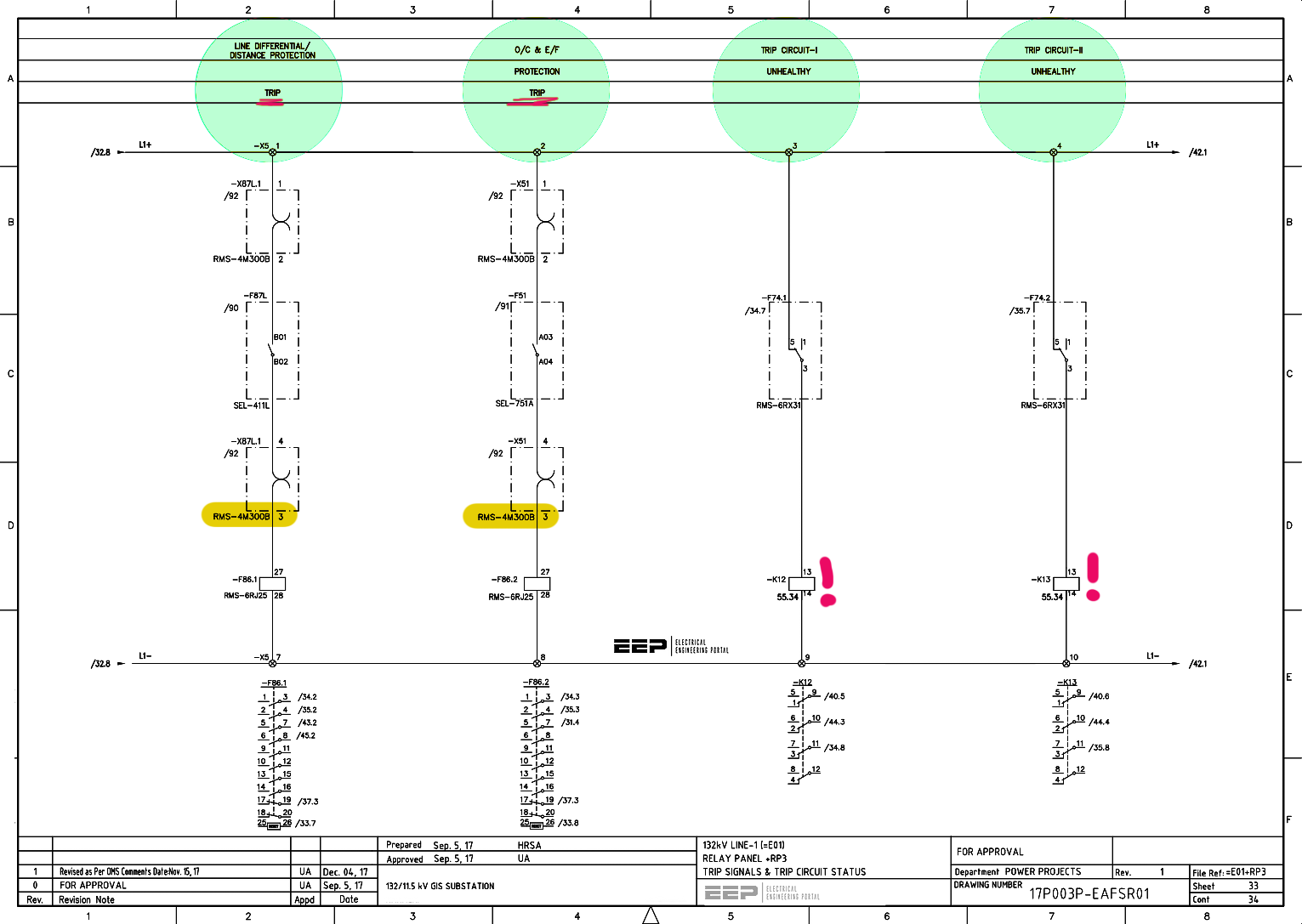
| Schematic drawings, also known as electrical or circuit diagrams, are essential tools for understanding and designing electrical circuits. Mastering schematic drawing is a fundamental skill for field engineers, allowing them to effectively troubleshoot, maintain, and modify electrical schemes. This technical article serves as a guided exploration through the core elements of schematic drawing, starting with the Single Line Diagram (SLD) and branching into detailed drawings that provide a comprehensive view of electrical circuits. From the standardized identifiers encapsulated in the ANSI Code to the graphical symbols representing various electrical components, we dissect the language of schematics. Crucial details such as Drawing Number, Panel Name, Revision Number, Project Name, and Page Identification are unraveled as indispensable components enriching the narrative of a schematic. As we navigate the organized world of schematics, the division of pages into rows and columns for efficient addressing becomes a cornerstone skill, complemented by techniques for cross-referencing and tracking inter-panel schematics. | 


Comments
Post a Comment